a1502 820-4924-A Liquid Damage... no image, but boots when Magsafe plugged in

papalati

Member
TLDR - Early 2015 MBP Retina was dropped and had liquid damage as well. When plugged in it turns itself on until manually forced off. No display and no external on hdmi as well.

Long story, bought a 13" a1502 Early 2015 and figured it had been dropped based on the listing. Little did I know it was dropped and had liquid damage in the corner near the lcd connector. The indicator in the middle of the board wasn't triggered. It arrived and I plugged the power in and it turned on by itself.

I'm assuming a short somewhere, but the screen stayed pitch black. I should have tried the flashlight trick to see if the backlight was out, but already had the board out by the time I remembered that as I wanted to try a known working board I had in it. The other board worked fine with the magsafe and also the screen obviously.

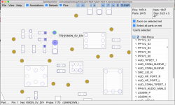
I've checked the board and the only thing I can come up with so far is a faulty FDC638APZ IC but still waiting for the chips to come in. So, I'm not sure where to go from here on the magsafe triggering the laptop on. Was considering putting it in my ultrasonic to clean it up before I get started again tracking down the issue.

What do you guys think?
 

2informaticos

Administrator
Staff member
"a faulty FDC638APZ IC "
You should mention schematic position, not component model.
Then we can make more exact idea about what you talk...

Test the board alone on the desk, only charger connected.
Need one USB device, if you get voltage on the CPU coils. to check for USB activity.
Dropped board is always nightmare; adding liquid spill, you are probably wasting time on it.
As is your personal machine, you can gain experience with it at least...
 

papalati

Member
Thank you for the information. I will try to do better. I am very new to doing apple logic boards. I've only done game consoles and other handheld devices.

I am using a good / working logic board to compare to the bad one to help me with readings as I'm a novice at best when it comes to reading schematics.

The biggest difference I'm seeing right now is at Q7701 at the 3rd pin from the left on the bottom and at Q7700 at pin 6 (.477) as it doesn't match Pin 1 at C7711 (97.3) like Pin 6 (145.6) matches Pin 1 (145.6) on the good board.

I'm using a pretty cheap multimeter, but I started with Q7701 and backtracked through and got to c7711.

The bad board shows:

At Q7701
In boardview it shows only a 5 at the bottom of the chip for the pins, but from left to right the readings for the 4 pins are.
1st pin = 97.3, 2nd pin = 2.08, 3rd pin = 97.3, 4th pin = .47 (The 3rd pin here matches the first pin, but on the good board, the 3rd pin matches the 4th pin.)

At Q7700
Pin 3 = 86.2
Pin 2 = 2.05
Pin 1 = .475
Pin 5 = 2.10
Pin 6 = .477

At C7711
Pin 1 = 97.3


The good board shows:

At Q7701
From left to right, 1st pin = 145.6, 2nd pin = 1.92, 3rd pin = .53, 4th pin = .53

At Q7700
Pin 3 = 85.7
Pin 2 = 148.3
Pin 1 = 1.86
Pin 5 = 1.84
Pin 6 = 145.6

At C7711
Pin 1 = 145.6

I hope this helps even just a bit to helping get me going in the right direction.
 

2informaticos

Administrator
Staff member
"In boardview it shows only a 5 at the bottom of the chip for the pins, but from left to right ..."
You make the things to look more complicated than they are!
Use signal names from schematic/boardview; this way avoid any confusion.
You do NOT need to mention any space direction, you are not examined for driver license here.
Our help is based on the information provided by you; so be more clearest posible, please.

As for example,
"At Q7701
From left to right, 1st pin = 145.6 "
there is in fact pin 4/Q7701, which MUST be mentioned as LCDBKLT_FET_DRV_R.
I have no idea if you posted a value measured on ohm scale, or diode scale (expected).
ALWAYS start measuring in diode scale, red probe at ground; sometime need to invert probes, for second reading!

On the other side, I wonder how can you get different readings in the same line¡¿?!
"2nd pin = 2.08, 3rd pin = 97.3, 4th pin = .47
----------------------------
2nd pin = 1.92, 3rd pin = .53, 4th pin = .53"
There should be LCDBKLT_SW, if your space reference is correct.
I don't talk about board differences.
In the same board, these three pins MUST get same reading; as all are connected to the same rail.

"Need one USB device, if you get voltage on the CPU coils. to check for USB activity. "
Do NOT waste the time searching for image/backlight, if you do not get voltage on CPU VCORE coils (L7310/20).
USB activity is also required to be confirmed first...
 

papalati

Member
"In boardview it shows only a 5 at the bottom of the chip for the pins, but from left to right ..."
You make the things to look more complicated than they are!
Use signal names from schematic/boardview; this way avoid any confusion.
You do NOT need to mention any space direction, you are not examined for driver license here.
Our help is based on the information provided by you; so be more clearest posible, please.

As for example,
"At Q7701
From left to right, 1st pin = 145.6 "
there is in fact pin 4/Q7701, which MUST be mentioned as LCDBKLT_FET_DRV_R.
I have no idea if you posted a value measured on ohm scale, or diode scale (expected).
ALWAYS start measuring in diode scale, red probe at ground; sometime need to invert probes, for second reading!

On the other side, I wonder how can you get different readings in the same line¡¿?!
"2nd pin = 2.08, 3rd pin = 97.3, 4th pin = .47
----------------------------
2nd pin = 1.92, 3rd pin = .53, 4th pin = .53"
There should be LCDBKLT_SW, if your space reference is correct.
I don't talk about board differences.
In the same board, these three pins MUST get same reading; as all are connected to the same rail.

"Need one USB device, if you get voltage on the CPU coils. to check for USB activity. "
Do NOT waste the time searching for image/backlight, if you do not get voltage on CPU VCORE coils (L7310/20).
USB activity is also required to be confirmed first...

As stated before, the computer boots to the chime even on the bad board, the screen is black with no hdmi external.

I wanted to first find out how to fix the fact that when you connect an ac adapter to it the computer boots by itself.

Then I wanted to find out how to restore the image/backlight.

That's it. I was hoping someone might have seen this before or just know already and say oh, you should look in this area for a cap or fuse to be blown which is causing it to boot immediately when connecting the ac adapter.

You can clearly tell, that I'm not an expert at this, but damnit I'm willing to try and learn it. I have 10+ years of service experience with a fortune 100 company on the software side of things, but not on the hardware component side. As a hobby, I've repaired boards with damaged traces or bad caps in game consoles, but half the time I couldn't tell you the difference between a resistor and a diode by looking at a board let alone what they do without googling it.

Until I got this bad board, I've never even opened up boardview. All I've done is replace them entirely and assign the serial numbers to the boards. That's it. I want to learn how to do it and I've always learned hands-on.

I'm sorry, I'm not using the right terminology. I'm sorry I'm not saying things the right way. I'm sorry I'm not providing the information that all you guys are used to hearing and sharing with each other in certain verbiage.

I lost my damn job, because of this pandemic. I've been trying to pick up work doing repairs for people and that is how I got stuck with this board. I'm trying my best with what littles skills and tools that I've got.

I'm sorry.
 

2informaticos

Administrator
Staff member
"No display and no external on hdmi as well "
That is the reason I asked about USB activity.
Missing internal and external video at same time, looks more like stuck board.

"As stated before, the computer boots to the chime even on the bad board "
NO, you've mentioned about ANOTHER working board, tested in the same case.
"The other board worked fine with the magsafe and also the screen obviously "

I'm really sorry if you got annoyed, was not my intention.
I just wanted to mark your wrong assumptions.
If you consider that is not for you help, dismiss such advise.

We try to start again.
First confirm USB activity on the first (bad) board.
Chime is not always sufficient.; board can get stuck after chime, before sending any image.
You've reported missing internal/external video at same time and is not too much reason to suspect a problem with backlight.

"I wanted to first find out how to fix the fact that when you connect an ac adapter to it the computer boots by itself. "
Not first, nor last.
I didn't say anything about that before, as it is normal behavior for any iCore MacBook.
 

papalati

Member
I think it might be your word usage and the use of your CAPS as it comes across as you scolding/yelling at me, when all I'm trying to do is seek some help. On top of that I am also having trouble understanding your English at times as well. It is very blunt and brash, but please understand that I do appreciate the fact that you've taken time to at least reply to me when no one else has.

As you said, let's start again.

Could you please elaborate on what you mean by stuck board? As the term stuck is very vague.

I will test for usb activity and voltage on the cpu coils and get back to you with that.
 

2informaticos

Administrator
Staff member
Sorry, english is not my native language.
Is on third place, after romanian and spanish.

We have to distinguish somehow between working boards and boards turned on.
Not any board which turns on, also works.
If we get any voltage from S4 to S0 state, that board is turned on; S5 state corresponds to off state.
If we miss some important voltage from S4 to S0 state, the board can stay on, but will not work properly; its behavior will depend by missing volage.
Hearing the chime is sign the board really boots, but it can get blocked in some point; just before getting video, for example.
If you see Caps Lock LED reaction for example, that means is not stuck; that board really works.
You can have then a problem with image/backlight.
When we repair a board alone on the desk, the best way to test is using an USB device; many times an USB mouse is good enough (not always).
 

2informaticos

Administrator
Staff member
VCORE looks good.
Do you get USB activity now?
Disconnect/reconnect USB mouse when board is turned on; mouse get steady light again?
 

papalati

Member
No external video on both DP ports on bad board.

Tested same setup and getting signal from good board.

So definitely no external video signal being sent to the monitor on bad board.

Yes, the board is out of the chassis.
 
Last edited:

2informaticos

Administrator
Staff member
If there is USB activity for sure, you have a problem with Intel graphics.
And shouldn't be related only with internal, or external video outputs, as both are missing.

Did you take a photo of the liquid affected areas, before cleaning the board?
Some return from backlight voltage could have been killed the iGPU.
When you start the board with internal LCD connected, check for voltage at R8320 pads.
You should also get voltage there in the first few seconds at least, even without LCD.
Keep the multimeter probe connected there when turn on the board; especially when hear the chime...
 
Last edited:

papalati

Member
Haven't put the board in the ultrasonic yet, Crest sent me the wrong one and it's too small.

Finally got it under the scope and there is heavy corrosion inside both display ports and only the liquid damage indicator by the lcd connector is activated. The others are still white. It's like someone dipped the corner of the laptop in water near the lcd connector.

I'll do the other tests later tonight or tomorrow and get back to you.
 

papalati

Member
Well... I went piece by piece through the board through the scope and found corrosion also on one other little piece and apparently a very important one as after I scraped the corrosion off and checked for continuity external video has been restored with a question mark folder showing :D

I think it's the power delivery system for the video maybe? Not sure since I don't read schematics obviously. Going to put it back in the chassis and test again.

I'll attach a pic from board view of the questionable point on the board.
 

Attachments

  • Screen Shot 2020-06-18 at 10.06.03 PM.png
    Screen Shot 2020-06-18 at 10.06.03 PM.png
    181.5 KB · Views: 7

papalati

Member
Okay another update.

External Video is only working via the DisplayPort. Also, tested the IO board for the USB and HDMI and no signal coming from the HDMI port and no USB activity either.

Going to try and figure it out while waiting for your feedback
 

2informaticos

Administrator
Staff member
Seems that you had corrosion on ALL_SYS_PWRGD circuit.
Q8150 can be removed to bypass similar problem; is just a redundant protection.

Onboard USB port doesn't work too?
Did you connect the both cables between MLB and RIO boards?
 
Top